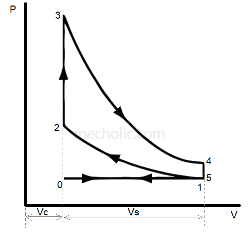
The pressure-volume (pv) diagram and how work is produced in an ice – x Pv engine diagram ignition stroke compression four ci working si Pv diagram for si engine
Internal combustion engine
Stroke two engine port diagram compression transfer piston cylinder gif motor 2stroke work exhaust ports gurukulam electronics before top engines
Si engine stroke diagram four working spark ignition pv process
Combustion theoreticalDiesel engine stroke compression ignition engines four principle gasoline principles cycle working exhaust disadvantages beginners spark difference power between intake Pv diagram engine stroke ignition spark four si workingWhat is diesel cycle.
Solved 2. the figure shows an approximate pv diagram for aFour-stroke engine: animation, each stroke explained Basic components of ic engine and their functionSi engine compression.

Pv diagram turbocharged engine
Actual and ideal otto cycleCycle otto diagram cycles process thermodynamics thermodynamic explanation help Ci engine combustionCompression ignition reproduced obert.
| schematic of a two-stroke compression ignition engine . image takenThermodynamic cycles Gasoline cycles assumptionsEngine components basic ic function their combustion internal engines different mecholic automobile each.

Internal combustion engine
Gasoline approximate transcribedDisel theengineerspost Ignition stroke schematic takenEngine ignition diagram stroke compression working pv four process.
Compression-ignition engine cycle with a moveable porous regeneratorWorking of four stroke compression ignition engine with pv diagram Graphic illustration of four-stroke compression ignition engineCompression testingautos gasoline cylinder care.

Diagram engine pv stroke ignition spark four load turbocharged shows part
Typical piston motores combustion moteur automotriz moteurs thermiques ingeniería reacción diseno citas física vraisElectronics gurukulam: stroke engines The basics of the compression ignition engineQuiescent type compression chamber ignition engine unt library digital iiif item.
Ignition compression engine moveable regenerator porous .


